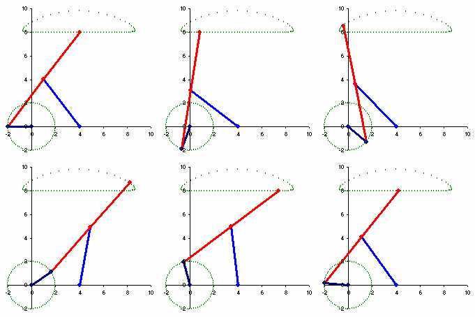
This linkage is a special case of a four bar linkage system where it converts rotational motion into constant linear motion in such a way as to produce an approximate stepping motion. This motion could be used to provide the mechanism for a walk, a conveyor belt, or other types of modified stepped motion.

We'll look at creating a rig in Maya that will produce a convincing representation from the above principle.
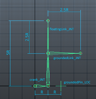
This system is all about proportions, all taken from the radius of the crank. The crank is the armature that desribes the initial circular motion and it is used to drive the whole system. We'll call the length of this crank R, which is the radius of the driving wheel. We can now express the other lengths of the components in multiples of R.

Connected to the crank is the floating link. This connects the input to the output of the system and is 5R in length.
Connected to the middle of the floating link is the grounded link. This will be pinned to the same space at the crank at a horizontal distance of 2R from it and is used to constrain the floating crank in a desirable way. The grounded link is of length 2.5R and is connected to the mid point of the floating link. Incidentally, the fourth bar of the linkage is the overextended floating link, but in this example it is considered as part of the floating link.
So how does this translate in Maya? We'll use a joint for the crank and connect two joints to this, one for the floating link and one for the IK chain that we'll use to restrict the floating link's movement. We'll pin the IK chain to the ground and we'll add and point constrain a locator at the end of teh floating link to visualise the output. We'll then add a couple of expressions to give it some life.
Let's create the joints. Choose the front view (in a Yup World), open up the script editor, clear the python tab and type the following...
import maya.cmds as mc

crankRadius = 1.0

# Create the joints
crank_JNT = mc.joint(n='crank_JNT', p=(0, 0, 0))
floatingLink_JNT = mc.joint(n='floatingLink_JNT', p=(crankRadius, 0, 0)  )
floatingLink_NULL = mc.joint(n='floatingLink_NULL', p=(crankRadius, crankRadius * 5, 0)  )
mc.pickWalk( direction='up')
groundedLink_JNT = mc.joint(n='groundedLink_JNT', p=(crankRadius, crankRadius * 2.5, 0)  )
groundedLink_NULL = mc.joint(n='groundedLink_NULL', p=(crankRadius * 3.5 , crankRadius * 2.5, 0)  )

# Orient the Root joint
mc.joint([crank_JNT], e=True, zso=True, oj='xyz')
We've chosen a crankRadius of 1.0, this is the main variable for the system and dictates the scale of the system
Next we need to add the IK to the groundedLink_JNT, constrain it to the groundedPin_LOC. While we're at it, we'll add a locator for the 'foot'
# Orient the Root joint
mc.joint([crank_JNT], e=True, zso=True, oj='xyz')

# Add the iK
groundedLink_IK = mc.ikHandle(n='groundedLink_IK',sj=floatingLink_JNT, ee=groundedLink_NULL)

# And the grounded pin locator
groundedPin_LOC = mc.spaceLocator(n='groundedPin_LOC')
mc.move(crankRadius * 2,0,0,groundedPin_LOC)

# Pin the leg with the constraint
mc.pointConstraint(groundedPin_LOC,groundedLink_IK[0],offset=(0,0,0), weight=1)

#add the foot locator
foot_LOC = mc.spaceLocator(n='foot_LOC')
mc.pointConstraint(floatingLink_NULL,foot_LOC,offset=(0,0,0), weight=1)

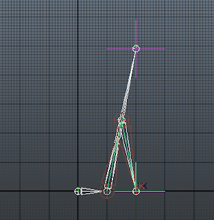
You should see the same in Maya as the image above.
Now we'll add some movement using a simple expression.
#add the control expression
exp = 'crank_JNT.rotateZ = frame * 10;'
mc.expression(string = exp,name = 'constantMotor')
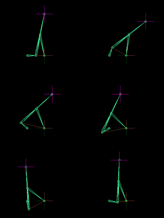
You should set the timeline range to something like 500 frames. We'll create a simple expression to rotate the crank based on the frame number, nothing more sophisticated is needed as the system will do the rest. I've used a 10x multiplier but you can add what you want.

Remember I said an approximate stepping motion. The values we've chosen are optimal but not exact to achieve true linear motion, however, it's good enough.
Now for some fun. Let's breath some life into it and make it translate.
#create the motor expression
exp =  'float $prevX = `getAttr -time (frame-1) {0}.tx`;'.format(foot_LOC[0])
exp += 'float $delta =  {0}.translateX - $prevX;'.format(foot_LOC[0])
exp += 'if ({0}.translateY >{1} && {0}.translateY <{2})'.format(foot_LOC[0], (4 * crankRadius - crankRadius/100),  (4 * crankRadius + crankRadius/20))

exp += '{'
exp += '{0}.translateX = {0}.translateX - $delta;'.format(crank_JNT)
exp += '{0}.translateX = {0}.translateX - $delta;'.format(groundedPin_LOC[0])
exp += '};'

mc.expression(string = exp,name = 'crawler')
It's quite a simple calculation, we're getting the difference (delta) of the x transform from the last frame to the current frame of the foot_LOC, and applying it to the crank and the groundedPin. We only do this when the foot_LOC is at the height that it's displaying linear behaviour. This height is 4R and we're using a -ve 1% and +ve 5% tolerance to clamp it's movement.

Try setting the timeline range from frames 15 to 20, set the playback looping to oscillate.
Thanks, was very helpful
ReplyDeleteNice work (Y)
ReplyDeletethank you so much really very very helpful
ReplyDeleteNice work ... Perfect
ReplyDelete