 |
| figure 1 |
A recent project I worked on required the modelling of an animating crank and a piston similar to those used by steam locomotives. Engines that use pistons as a power source need a way of converting the back and forth (reciprocating) linear piston motion into rotational motion. Cranks are used to do this and these are connected to points that are offset from the main rotational axis on what is called the crankshaft, and these in turn are connected to the pistons. The crankshaft is the part that receives the rotational energy. The system will also work in reverse, turning the rotational movement into linear.
So that's how it works in the real world, so how do we translate this into Maya?
For our purposes, we'll use the rotating crankshaft to drive the animation and there's a few ways we can go about this; using constraints, using set driven keys or using expressions. Using constraints will only get you part of the way and as you develop it, you'll find there'll be an issue with cyclic dependencies. So you'll constrain the piston to the rod, but you also need to constrain the rod to the piston and even using controllers or parenting this will still cause the same cyclic dependencies that result in evaluation errors and nasty jittering. I've tried all sorts of ways but couldn't create a viable solution. So another way would be to use set driven keys, but you'll need to use a lot of them in order to describe the motion accurately. At best you'll only achieve an approximation. However, if cheap and nasty works in the context of your requirements then fine, use whatever works. If you want to know how to do it properly, read on.
Expressions (unfortunately) are the only way we can solve this accurately. It's not cheap (you'll need to invest in some maths) but the result is a perfect system that's smooth and completely predictable.
I don't usually advocate the use of expressions and try and avoid them like the plague; they can be too rigid and restrictive in an animated workflow, locking nodes onto coded 'rails' and initiating behaviours that are hard to break away from. However, a system such as a crank and piston is ideal for this method; the system is completely closed (unless you plan to decompose the system later) and is a perfect example of how we can use expressions correctly and mathematically model the reciprocating motion. Just because I don't like using them, doesn't mean I won't and after this exercise I must say I am feeling just a little bit of love for Maya's expressions.
The crankshaft is the assembly that rotates, the piston is the assembly that only moves in one axis, and the connecting rod is the linkage that connects them both together and transfers the rotational energy into linear motion.
In order to work out the position of the piston, we'll need to find out how much the connecting rod needs to be rotated by in order to keep the piston horizontal. Once we have that angle, we've got our solution, and this solution comes from our mathematical knowledge of triangles.
So here's the investment part, the maths...
 |
| figure 2 |
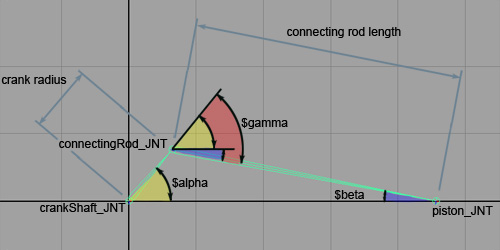
As the crankShaft_JNT rotates ($alpha), we need to work out the relative angle ($gamma) needed for the connectingRod_JNT to let the piston_JNT remain in a fixed horizontal axis. In our case, the piston_JNT can only move in the X axis. We know the crank radius and the connecting rod length, so we can use triangles and trigonometry to find $gamma by application of the Sine Rule to find $beta.
crank radius / sin $beta = connection rod length / sin $alpha
Re-arranging this equation to find $beta..
$beta = arcsin (connection rod length / (sin $alpha * crank radius))
And using another rule; pairs of angles with parallel lines (transversals), we can find $gamma(red on figure 2) from $alpha (yellow on figure 2) and $beta (blue on figure 2).
$gamma = $alpha + $beta
Note, we'll have to negate $gamma as an anticlockwise angle is needed. See the right hand grip rule for how to work out which way something will rotate.
Below we have an example script to create this system using Maya's joints and an expression which will explain it further. Cut and paste it into Maya's script window and execute it.
import maya.cmds as mc

#settings
crankRadius = 1
connectionRodLength = 4
expressionName = 'crank'

# Create the components
mc.joint(n='crankShaft_JNT', p=(0, 0, 0))
mc.joint(n='connectingRod_JNT', p=(crankRadius, 0, 0)  )
mc.joint('crankShaft_JNT', e=True, zso=True, oj='xyz')
mc.joint(n='piston_JNT', p=((connectionRodLength + crankRadius), 0, 0) )
mc.joint('crankShaft_JNT', e=True, zso=True, oj='xyz' )

#create throttle attribute on the crank
mc.addAttr('crankShaft_JNT', longName = "throttle", attributeType='double')
mc.setAttr('crankShaft_JNT.throttle', edit=True, keyable=True)
mc.setAttr('crankShaft_JNT.throttle', 200)

#expression syntax
exp = 'crankShaft_JNT.rotateY = time * crankShaft_JNT.throttle;'
exp += 'float $alpha = crankShaft_JNT.rotateY;'
exp += 'float $beta = asind((%s * sind($alpha) / %s));' % (str(crankRadius), str(connectionRodLength))
exp += '$gamma = -1 * ($beta + $alpha);'
exp += 'connectingRod_JNT.rotateY = $gamma;'

#create the expression
mc.expression(string = exp,name = expressionName);
You should see the the following result in the top view after hitting play..
 |
| figure 3 |
I've connected the crankShaft_JNT.rotateY to the time attribute, and together with this I've used a throttle attribute on this joint to control the speed. The expression should be simple to follow using the simple maths above as reference.
So there you have it, a completely perfect simulation of a crank and piston. Just parent constrain your geometry, group it all and move into position.
Please feel free to drop me a line if you need anyhing else from this.
Hi, just wanted to say nice explanation and example on the piston but I wanted to suggest an alternative idea.
ReplyDeletecreate the joints as you did.. create an ik handle from the second to the 3rd joint. point constrain the ik handle with maintain offset on, in just x/z but not Y, to the second joint. Rotate the first joint. It gives you the same effect of the piston being pulled but just using ik to calculate the angle.
Hi Brad, thanks for the suggestion. Nice neat trick using the IK. I did look at a similar system, but it suffered from the same accuracy errors, with the maximum error introduced when the angle between the two joints is at 90 degrees. However, your solution is a two minute job that for most cases will work just fine, so for getting the job done with the least amount of faff, I'd use yours ;)
ReplyDeleteBtw, enjoyed the video #rigTip Constraint hack - crank and pistons 101, thanks for the mention.
Thanks for watching,as you know It isn't at all accurate compared with the nice math work you did, but the little wiggle is liveable, though I still like this post and I realized I never posted the link over on the video as people point out that it isn't perfectly keeping the Y in place.
DeleteHi Paul,
ReplyDeleteThe tutorial on rigging the crank and piston was interesting and really useful.
A question to run by you, Im trying to animate the end of an hydraulic arm at work and seem to be struggling. Its the douboule linkage in the bucket area.
http://www.parker-hire.co.uk/images/micro.jpg
do you have any suggestions as to how you would rig that area?
Hi, in this example I would look at using the bucket as the driver for the rig. Set it's pivot correctly, then create a 3 joint IK skeleton with the root parented under the bucket at the rear bracket pivot, and the IK handle parented under the bracket pivot on the boom. I would then aim constrain the piston to a locator that is in turn point constrained to the 'elbow' of this skeleton, and parent the other end of the piston to the boom. Animate the bucket, and the piston should look like it's driving it, at least it does in the Maya scene I knocked together.
DeleteHope this helps, let me know how you get on.
Ok im with you that makes sense, Ill try it out and get back to you on that.
DeleteThankyou for your help!
hi
ReplyDeletesir
I am not understand this crank effect.
pls sir send the any video.
my email -id :prembonakruti@gmail.com
i would use a spline-IK, really easy to set up and even able to go arround corners.
ReplyDeleteset up the joints as they are in the example and put a spline-IK in the second and last joint.
cluster the first vertex of the spline curve and parent it to the rotation control, cluster the other vertices and parent them on the object it needs to follow. make sure that those vertices are placed in such a way that they follow the object.
if you rotate the control now, the second joint will always be placed on the base of the spline curve, the 3rd and last joint will follow the rest of the curve. easy setup and no constraints.
Hi Perry,
DeleteNice use and adaptation of the splineIK.
Just wondering, in this particular case, how would you get the motion of the piston that the IK needs to follow? I've looked at a few ways and maybe you've worked out another way of achieving this?
https://docs.google.com/file/d/0B4SWnZtPyt_OanJWc2dxX01TZEk/edit?usp=sharing
Deletethis was my first setup, its similar as the one by the new tutorial from rigging dojo, but a little bit different
That's a really nice way of using splineIK, it's giving me a few ideas.
DeleteI'm currently developing a locus constraint node to help with mechanical rigging, and this provides another solution for the crank and piston problem. It should also cater for sliding joints and cams and other geometrical and physical constraint problems.
Thanks for you post.
Perry, good tip on the spline IK, I used a spline ik in another test but your version is a little bit diffrent, worth a test to check it out.
ReplyDeleteThe piston does not maintain its horizontal pose, keeps rotating. What can i do for this?
ReplyDeleteHi Anonymous,
DeleteHow did you attach the piston to the piston_JNT? I suspect you parented your geometry to the joint?
I would use a point constraint, then I would only get the translation I needed.
You could also parent constrain it using only translation, or just connect the x translate channel of a parented node on joint to your geometry.
Lots of ways to do this however, parenting won't work in this case.
Of course! why didn't i think of that...thanks a lot on that info...btw you're a genius...seriously. Thanks again.
DeleteRigging Dojo #rigTip May Rig a crank and pistons 101 update: http://youtu.be/goKGOwgh52I Finally got around to doing a quick update after trying out the spline IK one more time. Thanks to Perry Leijten for promting another look at spline ik.
ReplyDeletethks!
ReplyDeleteI'm a little bit stuck. Getting my machine up to speed works wonderful but getting it to a halt is another story. Lovering the throttle value results in a rewind of the rotary movement. I've tried to solve this by myself but it seems like I can't wrap my head around the ways things are connected to each other. A little bit of help would be really appreciated.
ReplyDeleteAny way, thanks for this guide. I really enjoyed the fact that it didn't just scratch the surface as many others do.
Hi Pontus,
DeleteI added the connections to the time just to illustrate this example. I often hook up this sort of thing to save me animating. The throttle control was just a way playing with the control, again to save me animating it.
By lowering the throttle, do you mean reversing it or just slowing down, i.e. decreasing the value towards 0? Looking at it again a bit more thoroughly, when both the throttle and frame number have negative values the system does indeed break. Thanks for pointing this out.
So I'd either just animate the crankShaft_JNT.rotateY and delete the throttle control, or if you use the system as is, stick to the positive side of the timeline. It's probably not worth expanding on the expression to cater for what is mostly an avoidable situation.
Let me know how you go.
Paul