
Turning a car is not as simple as you think. There's some quite advanced geometry at work to order to maintain the correct rotations for each front wheel in order to keep the turn 'on track'. The radii for each wheel change at a non-linear rate as the turn gets sharper.
A best practical solution is the Ackerman Steering Principle, a well documented system. Whilst not 100% perfect, it's pretty much near to and as it's used on most vehicles today, this is what we'll use as our template. No bodging here I'm afraid. For more reading and theory that I will explain here, there's an excellent Wiki page on this Ackerman Steering Geometry.
So this system uses an axle pivot to base all measurements from, i.e. the front wheels are turned so that their axles point to a centre point that is in-line with the rear axle. (image from wiki)
Ackermann angles and geometry

Note, for the wheels to turn independently, they're mounted on two stub axles.
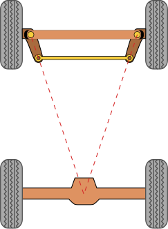
This is based of a trapezoidal linkage, the dimensions of such that will create an optimal steering trapezoid when the horizontal bar (track rod) is moved from side to side. The angle between the steering arm and track rods is what we need to replicate and is what we'll be calculating for the rig.
Simple approximation for designing Ackermann geometry
We'll be looking at setting up the front steering rig for a car using this geometry. I know there is a very simple solution where you can use set driven keys, or just have the wheels turn in parallel and if that's work visually then that's preferable and faster. However, if you're anal retentive about such things, read on, and to be honest I don't think I've seen a rig that utilises the above system so here goes..
We'll be using constraints, IK'd joints, vector maths, control groups and utility nodes, plus some understanding of mechanical terminolgy which we'll pick up as we go along.
Rigging
We'll need four wheels, named frontLeftWheel_MSH, frontRightWheel_MSH, rearLeftWheel_MSH, and rearRightWheel_MSH in the correct positions. The car will be facing in the +Z direction, and all wheels will be equidistant from the world origin.
The car's width will be 6. This is known as the track.
The distance between the front and rear axles is known as the wheelbase and will be 8.

We'll need some other variables, the wheel width and outside radius, an offset for the king pin so we can position the root of the stub axle relative to the wheel and finally the lengths of the track rod and steering arm. It is the lengths of these two that will determine two crucial things; the rate of turn and how accurate the system is.
There's one other variable we'll need which I've called the steeringRatio, and this represents the ratio of turn of the steering wheel to the side to side movement of the track rods. In reality, this is fixed by rack and pinion gearing and an optimal value is sought.
The following script will create the wheels, move them into position and create locators in the key areas,
import maya.cmds as mc
import maya.OpenMaya as om

wheelRadius = 1.5
wheelWidth = 1
wheelBase = 8
kingPinOffset = 0.5
track = 6
trackRodLength = 1.25
steeringArmLength = 0.5
steeringRatio = -0.005

#create the wheels
frontLeftWheel_MSH = mc.polyPipe(n='frontLeftWheel_MSH',r=wheelRadius,h=wheelWidth,t=0.5,sa=24,sh=1,sc=8,ax=(1,0,0),cuv=1,rcp=1,ch=0)
frontRightWheel_MSH = mc.polyPipe(n='frontRightWheel_MSH',r=wheelRadius,h=wheelWidth,t=0.5,sa=24,sh=1,sc=8,ax=(1,0,0),cuv=1,rcp=1,ch=0)
rearLeftWheel_MSH = mc.polyPipe(n='rearLeftWheel_MSH',r=wheelRadius,h=wheelWidth*2,t=0.5,sa=24,sh=1,sc=8,ax=(1,0,0),cuv=1,rcp=1,ch=0)
rearRightWheel_MSH = mc.polyPipe(n='rearRightWheel_MSH',r=wheelRadius,h=wheelWidth*2,t=0.5,sa=24,sh=1,sc=8,ax=(1,0,0),cuv=1,rcp=1,ch=0)

#move them into position
mc.move(track/2,wheelRadius,wheelBase/2,frontLeftWheel_MSH)
mc.move(track/-2,wheelRadius,wheelBase/2,frontRightWheel_MSH)
mc.move(track/2,wheelRadius,wheelBase/-2,rearLeftWheel_MSH)
mc.move(track/-2,wheelRadius,wheelBase/-2,rearRightWheel_MSH)

From this setup, we can calculate correct ackerman angle for the trapezium. We need to find points for the steering arm pivot and the track rod pivot. We'll use vectors as it's the most appropriate, and we'll be using Maya's OpenMaya API MVector and MPoint Classes for this.
- Draw a line from a wheel to the rear axle centre.
- Mark along this line a distance of 'steering arm length' to find the steering arm pivot.
- From this point, find a point a distance of 'track rod length' along the x axis which is the track rod pivot.
#work out the steering arm pivot location with vectors
MA1 = (om.MPoint(0,wheelRadius,wheelBase/-2))
FL1 = (om.MPoint(track/2 - kingPinOffset,wheelRadius,wheelBase/2))

V = MA1 - FL1
length = V.length()
Vn = V.normal()

SteeringArmPt = MA1 - Vn * (length - steeringArmLength)

steeringArmLeftPvt_LOC = mc.spaceLocator(n='steeringArmLeftPvt_LOC')[0]
mc.move(SteeringArmPt.x,SteeringArmPt.y,SteeringArmPt.z,steeringArmLeftPvt_LOC)
trackRodLeftPvt_LOC = mc.spaceLocator(n='trackRodLeftPvt_LOC')[0]
mc.move(SteeringArmPt.x - trackRodLength,SteeringArmPt.y,SteeringArmPt.z,trackRodLeftPvt_LOC)

steeringArmRightPvt_LOC = mc.spaceLocator(n='steeringArmRightPvt_LOC')[0]
mc.move(SteeringArmPt.x * -1,SteeringArmPt.y,SteeringArmPt.z,steeringArmRightPvt_LOC)
trackRodRightPvt_LOC = mc.spaceLocator(n='trackRodRightPvt_LOC')[0]
mc.move((SteeringArmPt.x *-1) + trackRodLength,SteeringArmPt.y,SteeringArmPt.z,trackRodRightPvt_LOC)
What we've just done is create two MPoints; one for the mid axle point MA1 and one for the front left wheel FL1. V is the vector from the Mid Axle point to the wheel.
We find the length of this vector and the normal of this vector (Vn). We then subtract the steering arm length from this length, and multiply this by the normal vector to give us a relative vector from the mid axle point to the steering arm pivot. Subtracting this from the mid axle point gives us an actual point to locate the steering arm pivot on the left of the car. The right side is just negated in x. The track rod pivots are an easy calculation from these steering arm pivots.

Next, we'll use these pivot points to create a pair of 3 joint IK chains which will function as the track rods and steering arms. We'll constrain these to their corresponding locators, and not forgetting to link up the wheels by parent constraining them to their respective steering arm joints.
#build the joints
mc.select(cl=True)
leftTrackRod_JNT = mc.joint(n='leftTrackRod_JNT',p=(mc.xform(trackRodLeftPvt_LOC, query=True, translation=True)))
leftSteeringArm_JNT = mc.joint(n='leftSteeringArm_JNT',p=(mc.xform(steeringArmLeftPvt_LOC, query=True, translation=True)))
leftSteeringPivot_JNT = mc.joint(n='leftSteeringPivot_JNT',p=(mc.xform(frontLeftKingPin_LOC, query=True, translation=True)))
mc.joint(leftTrackRod_JNT, edit=True,orientJoint='xyz',secondaryAxisOrient='yup', children=True, zeroScaleOrient=True)
mc.select(cl=True)

rightTrackRod_JNT = mc.joint(n='rightTrackRod_JNT',p=(mc.xform(trackRodRightPvt_LOC, query=True, translation=True)))
rightSteeringArm_JNT = mc.joint(n='rightSteeringArm_JNT',p=(mc.xform(steeringArmRightPvt_LOC, query=True, translation=True)))
rightSteeringPivot_JNT = mc.joint(n='rightSteeringPivot_JNT',p=(mc.xform(frontRightKingPin_LOC, query=True, translation=True)))
mc.joint(rightTrackRod_JNT, edit=True,orientJoint='xyz',secondaryAxisOrient='yup', children=True, zeroScaleOrient=True)
mc.select(cl=True)

#createIK
leftSteering_IK = mc.ikHandle( n='leftSteering_IK', startJoint=leftTrackRod_JNT, endEffector=leftSteeringPivot_JNT )
rightSteering_IK = mc.ikHandle( n='rightSteering_IK', startJoint=rightTrackRod_JNT, endEffector=rightSteeringPivot_JNT )

#constrain the IK
mc.pointConstraint(frontLeftKingPin_LOC,leftSteering_IK[0])
mc.pointConstraint(trackRodLeftPvt_LOC,leftTrackRod_JNT)
mc.pointConstraint(frontRightKingPin_LOC,rightSteering_IK[0])
mc.pointConstraint(trackRodRightPvt_LOC,rightTrackRod_JNT)

#constrain the wheels
mc.parentConstraint(leftSteeringArm_JNT,frontLeftWheel_MSH,maintainOffset=True,skipRotate=['x','z'],weight=1)
mc.parentConstraint(rightSteeringArm_JNT,frontRightWheel_MSH,maintainOffset=True,skipRotate=['x','z'],weight=1)

The system should work. If you move the track rod locators from side to side, you'll see the wheels move correctly.
Now to rig up some controls. We'll group the two track rod locators under one null node (steeringGroup_GRP) so we can control this as one. We'll create a nurbs circle for the steering wheel(steeringWheel_CTL), grouped under a null node (steeringCTLGroup_GRP) and moved and rotated into an appropriate position. We'll then created a simple node network from one MultiplyDivide node to connect the Y rotation of the steering wheel to the X Translation of the track rods group. We'll add a multiply value of steeringRatio (remember that?) to alter the ratio of movement.
#create controls
steeringGroup_GRP = mc.group(trackRodLeftPvt_LOC,trackRodRightPvt_LOC,name='steeringGroup_GRP')
steeringWheel_CTL = mc.circle(c=(0,0,0), nr=(0,1,0), sw=360,r=wheelRadius,d=3,ut=0,s=8,ch=0)[0]
mc.hardenPointCurve("{0}.cv[5]".format(steeringWheel_CTL),rpo=1, m=1)
mc.setAttr('{0}.rx'.format(steeringWheel_CTL),lock=True)
mc.setAttr('{0}.rz'.format(steeringWheel_CTL),lock=True)
steeringCTLGroup_GRP = mc.group(steeringWheel_CTL,name='steeringCTLGroup_GRP')
mc.move(track/-4,wheelRadius*2,wheelBase/4,steeringCTLGroup_GRP)
mc.rotate(-60,0,0,steeringCTLGroup_GRP)
mc.setAttr('{0}.overrideEnabled'.format(steeringWheel_CTL),1)
mc.setAttr('{0}.overrideColor'.format(steeringWheel_CTL),17)

#rig controls
mdNode_UTL = mc.shadingNode('multiplyDivide', asUtility=True, name='mdNode_UTL')
mc.connectAttr('{0}.rotateY'.format(steeringWheel_CTL), '{0}.input1X'.format(mdNode_UTL), force=True)
mc.connectAttr('{0}.outputX'.format(mdNode_UTL), '{0}.translateX'.format(steeringGroup_GRP), force=True);
mc.setAttr('{0}.input2X'.format(mdNode_UTL),steeringRatio)
Conclusion

However, there are other problems to be solved if this is to be deployed as part of a car rig. For example, if you lift one of the front wheels up by it's locator, you see we have an undesirable rotation in Y caused by the IK. This would happen if we rigged active suspension, and to solve it you'll need to rotate the track rods with the suspension, but that's not for now.
Here's the full script if you just want to run it and play.
# Paul Atkinson http://techartandstuff.blogspot.co.uk/ (c)2013

import maya.cmds as mc
import maya.OpenMaya as om

wheelRadius = 1.5
wheelWidth = 1
wheelBase = 8
kingPinOffset = 0.5
track = 6
trackRodLength = 1.25
steeringArmLength = 0.5
steeringRatio = -0.005

#create the wheels
frontLeftWheel_MSH = mc.polyPipe(n='frontLeftWheel_MSH',r=wheelRadius,h=wheelWidth,t=0.5,sa=24,sh=1,sc=8,ax=(1,0,0),cuv=1,rcp=1,ch=0)
frontRightWheel_MSH = mc.polyPipe(n='frontRightWheel_MSH',r=wheelRadius,h=wheelWidth,t=0.5,sa=24,sh=1,sc=8,ax=(1,0,0),cuv=1,rcp=1,ch=0)
rearLeftWheel_MSH = mc.polyPipe(n='rearLeftWheel_MSH',r=wheelRadius,h=wheelWidth*2,t=0.5,sa=24,sh=1,sc=8,ax=(1,0,0),cuv=1,rcp=1,ch=0)
rearRightWheel_MSH = mc.polyPipe(n='rearRightWheel_MSH',r=wheelRadius,h=wheelWidth*2,t=0.5,sa=24,sh=1,sc=8,ax=(1,0,0),cuv=1,rcp=1,ch=0)

#move them into position
mc.move(track/2,wheelRadius,wheelBase/2,frontLeftWheel_MSH)
mc.move(track/-2,wheelRadius,wheelBase/2,frontRightWheel_MSH)
mc.move(track/2,wheelRadius,wheelBase/-2,rearLeftWheel_MSH)
mc.move(track/-2,wheelRadius,wheelBase/-2,rearRightWheel_MSH)

#create the positional locators
rearAxleCentre_LOC = mc.spaceLocator(n='rearAxleCentre_LOC')[0]
mc.move(0,wheelRadius,wheelBase/-2,rearAxleCentre_LOC)

frontLeftKingPin_LOC = mc.spaceLocator(n='frontLeftKingPin_LOC')[0]
mc.move(track/2 - kingPinOffset,wheelRadius,wheelBase/2,frontLeftKingPin_LOC)

frontRightKingPin_LOC = mc.spaceLocator(n='frontRightKingPin_LOC')[0]
mc.move(kingPinOffset - track/2,wheelRadius,wheelBase/2,frontRightKingPin_LOC)

#work out the steering arm pivot location with vectors
MA1 = (om.MPoint(0,wheelRadius,wheelBase/-2))
FL1 = (om.MPoint(track/2 - kingPinOffset,wheelRadius,wheelBase/2))

V = MA1 - FL1
length = V.length()
Vn = V.normal()

SteeringArmPt = MA1 - Vn * (length - steeringArmLength)

steeringArmLeftPvt_LOC = mc.spaceLocator(n='steeringArmLeftPvt_LOC')[0]
mc.move(SteeringArmPt.x,SteeringArmPt.y,SteeringArmPt.z,steeringArmLeftPvt_LOC)
trackRodLeftPvt_LOC = mc.spaceLocator(n='trackRodLeftPvt_LOC')[0]
mc.move(SteeringArmPt.x - trackRodLength,SteeringArmPt.y,SteeringArmPt.z,trackRodLeftPvt_LOC)

steeringArmRightPvt_LOC = mc.spaceLocator(n='steeringArmRightPvt_LOC')[0]
mc.move(SteeringArmPt.x * -1,SteeringArmPt.y,SteeringArmPt.z,steeringArmRightPvt_LOC)
trackRodRightPvt_LOC = mc.spaceLocator(n='trackRodRightPvt_LOC')[0]
mc.move((SteeringArmPt.x *-1) + trackRodLength,SteeringArmPt.y,SteeringArmPt.z,trackRodRightPvt_LOC)

#build the joints
mc.select(cl=True)
leftTrackRod_JNT = mc.joint(n='leftTrackRod_JNT',p=(mc.xform(trackRodLeftPvt_LOC, query=True, translation=True)))
leftSteeringArm_JNT = mc.joint(n='leftSteeringArm_JNT',p=(mc.xform(steeringArmLeftPvt_LOC, query=True, translation=True)))
leftSteeringPivot_JNT = mc.joint(n='leftSteeringPivot_JNT',p=(mc.xform(frontLeftKingPin_LOC, query=True, translation=True)))
mc.joint(leftTrackRod_JNT, edit=True,orientJoint='xyz',secondaryAxisOrient='yup', children=True, zeroScaleOrient=True)
mc.select(cl=True)

rightTrackRod_JNT = mc.joint(n='rightTrackRod_JNT',p=(mc.xform(trackRodRightPvt_LOC, query=True, translation=True)))
rightSteeringArm_JNT = mc.joint(n='rightSteeringArm_JNT',p=(mc.xform(steeringArmRightPvt_LOC, query=True, translation=True)))
rightSteeringPivot_JNT = mc.joint(n='rightSteeringPivot_JNT',p=(mc.xform(frontRightKingPin_LOC, query=True, translation=True)))
mc.joint(rightTrackRod_JNT, edit=True,orientJoint='xyz',secondaryAxisOrient='yup', children=True, zeroScaleOrient=True)
mc.select(cl=True)

#createIK
leftSteering_IK = mc.ikHandle( n='leftSteering_IK', startJoint=leftTrackRod_JNT, endEffector=leftSteeringPivot_JNT )
rightSteering_IK = mc.ikHandle( n='rightSteering_IK', startJoint=rightTrackRod_JNT, endEffector=rightSteeringPivot_JNT )

#constrain the IK
mc.pointConstraint(frontLeftKingPin_LOC,leftSteering_IK[0])
mc.pointConstraint(trackRodLeftPvt_LOC,leftTrackRod_JNT)
mc.pointConstraint(frontRightKingPin_LOC,rightSteering_IK[0])
mc.pointConstraint(trackRodRightPvt_LOC,rightTrackRod_JNT)

#constrain the wheels
mc.parentConstraint(leftSteeringArm_JNT,frontLeftWheel_MSH,maintainOffset=True,skipRotate=['x','z'],weight=1)
mc.parentConstraint(rightSteeringArm_JNT,frontRightWheel_MSH,maintainOffset=True,skipRotate=['x','z'],weight=1)

#create controls
steeringGroup_GRP = mc.group(trackRodLeftPvt_LOC,trackRodRightPvt_LOC,name='steeringGroup_GRP')
steeringWheel_CTL = mc.circle(c=(0,0,0), nr=(0,1,0), sw=360,r=wheelRadius,d=3,ut=0,s=8,ch=0)[0]
mc.hardenPointCurve("{0}.cv[5]".format(steeringWheel_CTL),rpo=1, m=1)
mc.setAttr('{0}.rx'.format(steeringWheel_CTL),lock=True)
mc.setAttr('{0}.rz'.format(steeringWheel_CTL),lock=True)
steeringCTLGroup_GRP = mc.group(steeringWheel_CTL,name='steeringCTLGroup_GRP')
mc.move(track/-4,wheelRadius*2,wheelBase/4,steeringCTLGroup_GRP)
mc.rotate(-60,0,0,steeringCTLGroup_GRP)
mc.setAttr('{0}.overrideEnabled'.format(steeringWheel_CTL),1)
mc.setAttr('{0}.overrideColor'.format(steeringWheel_CTL),17)

#rig controls
mdNode_UTL = mc.shadingNode('multiplyDivide', asUtility=True, name='mdNode_UTL')
mc.connectAttr('{0}.rotateY'.format(steeringWheel_CTL), '{0}.input1X'.format(mdNode_UTL), force=True)
mc.connectAttr('{0}.outputX'.format(mdNode_UTL), '{0}.translateX'.format(steeringGroup_GRP), force=True);
mc.setAttr('{0}.input2X'.format(mdNode_UTL),steeringRatio)
Enjoy
Impressive! Thank You :)
ReplyDeletevery good! thank you!
ReplyDeleteLove it! This is by far the best front wheel setup i've ever seen :) Keep up the good work. Thank you!
ReplyDeleteCould you share the scene file? I'm new to maya and I can't execute the script... The script editor says there is a syntax error, I don't know
ReplyDeleteHi Damien, the script is all you'll need. Are you running it in the script editor as a MEL command? If so, create a Python tab in the script editor, and paste and run the last script above in there.
DeletePaul
Ah ok. Python. Thank you xD
ReplyDeleteHaha, a timely cross post makes it look like you read my post 2 minutes before I posted it.
DeleteGood luck with the script.
This comment has been removed by the author.
ReplyDeletecan we expect for an tutorial video on this rig
ReplyDeleteGreat and that i have a keen present: What To Expect When Renovating A House victorian renovation
ReplyDeleteamazed
ReplyDeleteGreat breakdown of power steering fluid and why regular checks matter. At Kwik Kar Auto Dallas, we see how small maintenance details connect to bigger issues like check engine light dallas, which drivers often overlook until it becomes urgent. Staying proactive with Auto Repair, Car Repair and maintenance, and overall Auto Care helps avoid warning lights and unexpected repairs. A trusted Auto Repair Shop or Vehicle Repair Shop can spot early signs through proper Automotive Repair Services, keeping Vehicle Repair, Car Maintenance, and Car Repair Workshop visits efficient. For many local drivers, check engine light dallas awareness is just as important as fluid care.
ReplyDeleteAwesome article. Thanks!
ReplyDelete